|

Creating a SOM Plot
Overview
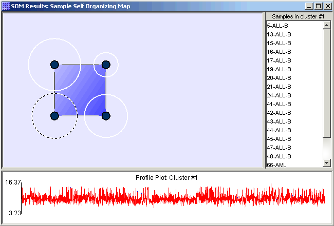
The SOM plot is a composition of a proximity-gradient map, a cluster membership list showing the items (samples/genes) contained in the selected cluster, and a node/cluster profile plot comparing node and cluster profiles.
The Proximity Gradient Map
The main part of the chart is the proximity-gradient map (it appears as the background in the upper-left hand pane of the chart). This proximity-gradient map is a high-level view of the average proximity (or similarity) between the reference vectors of the SOM. One end of the gradient is used to indicate areas of high average similarity, and the other end of the gradient indicates low average similarity.
Each node in the map is depicted as a small, filled-in circle, and each node represents a single cluster. The nodes of the map are numbered first from left to right, then from bottom to top. Nodes are numbered starting at one. You can see the node's number in a tooltip that appears when you hover the mouse pointer over that node in the map.
The dashed circles around the nodes, called cardinality rings , indicate how many items are contained in the cluster represented by the node. Nodes with the largest radius contain the most items. The selected node has a dashed cardinality ring and its items are listed in the cluster membership list.
The vertical and horizontal lines that connect adjacent nodes are collectively referred to as the proximity-grid. Just as the gradient-map shows the average similarity of nodes in particular areas, the proximity grid shows more accurately the similarity between adjacent nodes. One color indicates high similarity and another color indicates low similarity. Shades in between those two specific colors indicate intermediate degrees of similarity.
The Cluster Membership List
The list to the right of the proximity-gradient map is the cluster membership list. This list always shows the items (samples/genes) in the cluster represented by the selected node.
The Node/Cluster Profile
The plot below the proximity-gradient map is the node/cluster profile. This plot provides information about the map node and the cluster that it represents for the selected node.
The blue line in the plot is the profile of the reference vector of the selected node. The red line is the profile of the centroid of the cluster represented by that node. Comparing these two profiles allows you to determine how well the characteristic profile of the cluster matches the profile of the node.
The pink area behind the node and centroid profiles is the area of one standard deviation around the centroid. The size of that area indicates the fitness of the cluster. Large areas indicate low fitness and small areas indicate high fitness.
Actions
1. Double-click a SOM experiment in the Experiments navigator. The item is highlighted and a SOM plot of the selected item is displayed.
OR
1. Click a SOM experiment in the Experiments navigator. The item is highlighted.
2. Select SOM Plot from the Clustering menu, or right-click on the SOM experiment and select SOM Plot from the shortcut menu. A SOM Plot of the selected item is displayed.
Selecting a Node
1. Click on a node (cluster) in the proximity-gradient map (upper left of plot). The node is ringed by a rotating dashed circle. To the right, a list of the members in the cluster is displayed and below, there is a plot of the cluster profile.
Displaying a Cluster Plot of a Node
1. Click on a node to select it.
2. Select Cluster Plot from the Clustering menu, or right-click on the proximity-gradient map or on the profile plot and select Cluster Plot from the shortcut menu. A cluster plot of the selected node is displayed.
Using the Cluster Membership List Shortcut Menu
1. Right-click in the cluster membership list to display the shortcut menu. Select an item on the menu to activate that function.
Lookup gene in a database.
Related Topics:
Tutorial 4: Self-Organizing Maps